Personal collections

The circuit for a full-wave rectifier using four ideal diodes is shown in the figure below.

A resistor R is connected across the output AB of the rectifier.
The variation with time  of the potential difference
  across the input XY is given by the expression
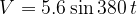
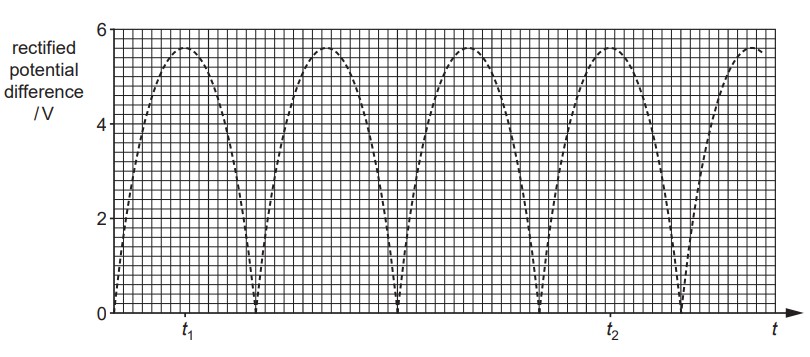
where is measured in volts and is measured in seconds. The variation with time of the rectified potential difference across the resistor R is shown in the graph below.
Use the expression for the input potential difference , or otherwise, to determine
the root-mean-square (r.m.s.) potential difference  of the input,
the number of times per second that the rectified potential difference at the output reaches a peak value.


 .
.