Personal collections

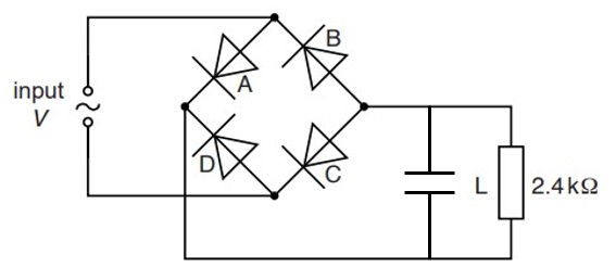
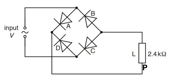
A bridge rectifier contains four ideal diodes A, B, C and D, as shown in the figure below.
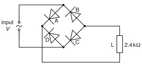
The output of the rectifier is connected to a load L of resistance  .
.
On the figure above, mark with the letter P, the positive terminal of the load.
The variation with time  of the potential difference
  across the input to the rectifier is shown in the graph below.
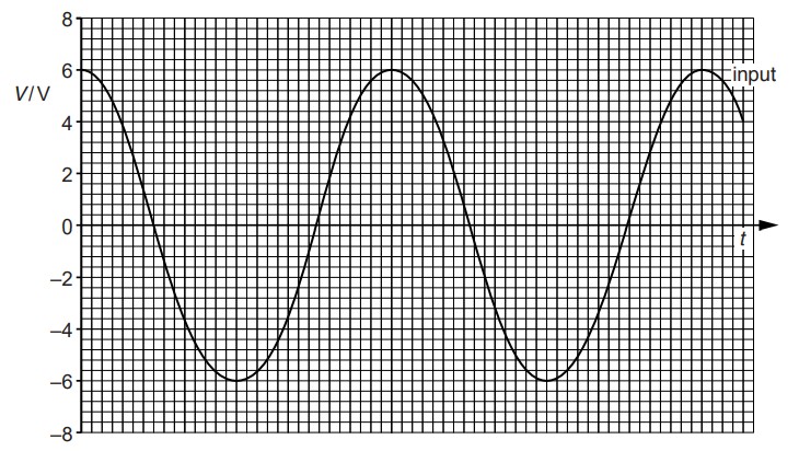
Calculate the root-mean-square (r.m.s.) current in the load L.
The potential difference across the load L is to be smoothed using a capacitor. On the figure above, draw the symbol for a capacitor, connected to produce smoothing.


 .
.