Personal collections

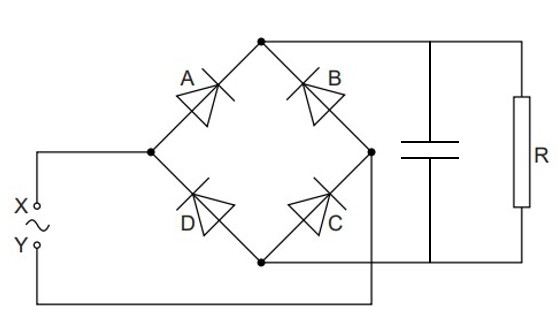
A bridge rectifier consists of four ideal diodes A, B, C and D, connected as shown in the figure below.
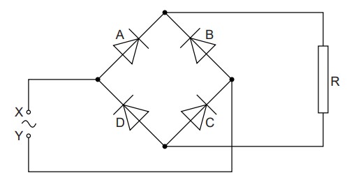
An alternating supply is applied between the terminals X and Y.
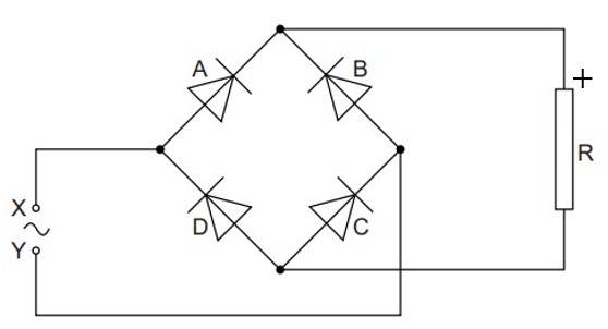
On the figure above, label the positive (+) connection to the load resistor R.
State which diodes are conducting when terminal Y of the supply is positive.
The variation with time  of the potential difference
  across the load resistor R is shown in the graph below.
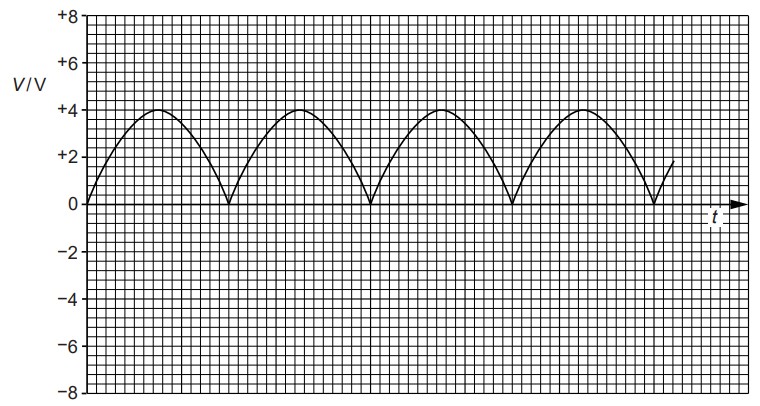
The load resistor R has resistance  .
.
Use the graph above to determine the mean power dissipated in the resistor R.
On the figure above, draw the symbol for a capacitor, connected so as to increase the mean power dissipated in the resistor R.


 .
.