Personal collections

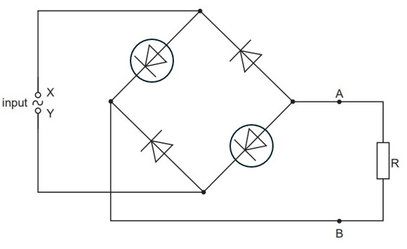
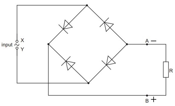
The circuit for a full-wave rectifier using four ideal diodes is shown in the figure below.
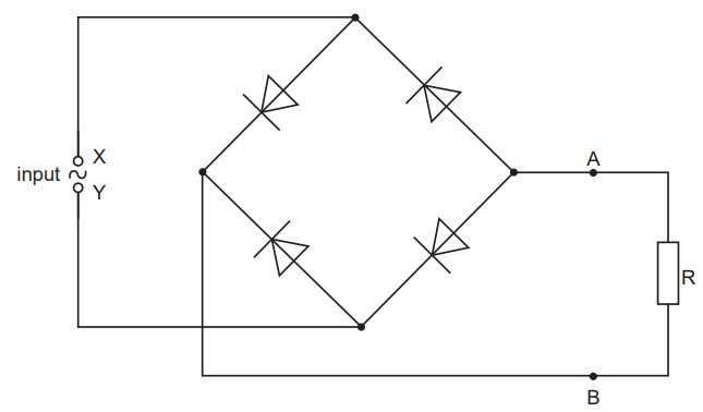
A resistor R is connected across the output AB of the rectifier. On the figure above,
draw a circle around any diodes that conduct when the terminal X of the input is positive with respect to terminal Y,
label the positive (+) and the negative (–) terminals of the output AB.