Personal collections

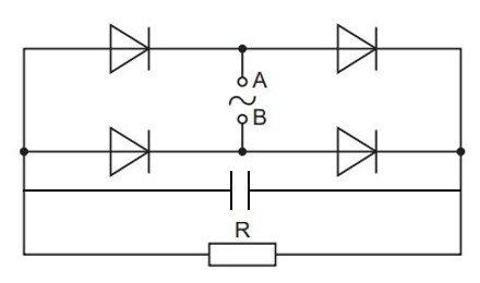
A bridge rectifier using four ideal diodes is shown in the figure below.
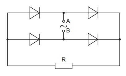
The sinusoidal alternating electromotive force (e.m.f.) applied between points A and B has a root-mean-square (r.m.s.) value of  .
.
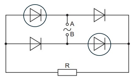
On the figure above, circle the diodes that conduct when point B is positive with respect to point A.
Calculate the maximum potential difference  across resistor R.
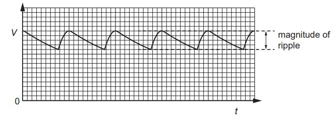
A capacitor is connected into the circuit to produce smoothing of the potential difference across resistor R. The variation with time  of the potential difference
  across resistor R is shown in the graph below.
On the figure above, draw the symbol for a capacitor, connected so as to produce smoothing.
State the effect, if any, on the magnitude of the ripple on when, separately:
a capacitor of larger capacitance is used
the resistor R has a smaller resistance.


 .
.