Personal collections

In the material, Electric current, we explained the mechanism of conduction of electric current through metal. We drew a model of the movement of free (valence) electrons, first without the presence of an external electric field. Then the direction of movement of these electrons in the metal is completely random, similar to the molecules of a gas or liquid due to heat. During their movement, they are constantly stopped by metal ions. When an electron collides with an ion, it joins it for a moment, the total charge of the ion is cancelled out, and immediately afterwards the electron moves in the other direction. Thus, the valence electrons in the metal structure are randomly rearranged.
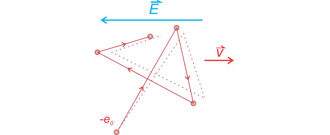
Figure 1: Electron motion in copper: solid line - no electric field, dashed line - in an electric field
In the presence of an electric field, the electrons, in addition to random rearrangement, also move against the direction of the electric field. This movement represents an electric current. Positive ions stop them from doing so. They represent resistance to the movement of electrons and thus resistance to electric current.
The conductor will present less resistance to the current if the mean time between two collisions is longer. This time depends on:
the distance between two collisions; this has to do with the type of metal, and
the speeds of thermal motion of electrons; this has to do with the temperature.
The purpose of this material is to learn about:
what the electrical resistance is and
how the electrical resistance affects the properties of an electrical circuit.
Electrical resistance is a physical quantity denoted by  . It tells us to what extent a substance hinders the motion of electrically charged particles, i.e. electric current. It depends on the substance, temperature, density of moving charge carriers, the viscosity of liquids, gas pressure, etc.
A substance with low resistance is called a conductor. A substance that has zero resistance is called a superconductor (some substances at low temperatures). A substance that has a very high resistance (near infinite) is called an insulator.
Electrical resistance is defined as the quotient of the voltage  across any element (resistor, light bulb, etc.) and the current
  through the same element.
An electrical resistor is an element in electrical engineering that has a certain resistance .
In the material, Electric current, we saw that the source voltage (we also called it the driving voltage) falls along the electric circuit. Most of the voltage fell on the consumer (also called the load), and a smaller part was also on the conductor that connects the voltage source to the consumer.
Let's imagine that the consumer is connected directly to the voltage source. The consumer should have a resistance . We change the source voltage and observe how the current through the load changes. Here we come to the relationship between voltage and current, which is called Ohm's law.
Ohm's law states that the change in voltage  across a load is directly proportional to the change in current
  . The proportionality constant is the resistance :

The resistance is therefore:

If the relationship between current and voltage is linear, we can omit the notation  :
:

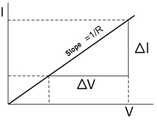
Figure 2: Linear dependence of current and voltage - Ohm's law
The unit of electrical resistance is  (ohm):

Ohm's law can be expressed in the following three forms:


A current node is a junction of three or more conductors which electric currents flow into or from. The directions of the currents are indicated by an arrow.
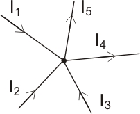
Figure 3: Example of current node
A voltage loop is a closed electrical circuit that may contain voltage sources, resistors, or other electrical elements.
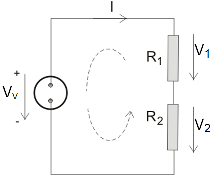
Figure 4: Example of a voltage loop
Kirchhoff's first law states that the sum of all currents in a node is zero. In this case, the currents flowing into the node are positive and the outgoing currents are negative.
It can also be stated in other words: At a node, the sum of the inflows is equal to the sum of the outflows.
Kirchhoff's first law: At a node, the sum of the inflowing currents is equal to the sum of the outflowing currents. If we have  currents, we can write symbolically:

where  is the number of inflows and outflows.
Kichoff's second law states that the sum of all voltages inside a closed loop is equal to zero. In the loop, we select the direction of voltage observation: e.g. clockwise direction. The voltages are marked with an arrow (the arrow is directed from the positive pole to the negative pole of the voltage). If the direction of the arrow matches the direction of observation, the voltage should be positive, otherwise, it should be negative.
It can also be said in other words: The source voltage is equal to the sum of the voltage drops across the load resistors.
Kirchhoff's second law: Within a closed loop, the sum of all voltages is zero. If we have voltages, we can write mathematically:

where is the number of elements in the loop.
Resistors can be connected in parallel, in series, or in a combination of parallel and series connections. The resulting connection of two or more resistors has a total resistance . If the connection is replaced by a single resistor with resistance , it is called a replacement resistor.
The total resistance is the resistance of a single resistor that has the same value as the resistance of the connection of two or more resistors.
Let's connect three resistors in parallel. The current flows from the source to the node, also called the junction of three resistors, and is divided into three branches, as shown in the figure.
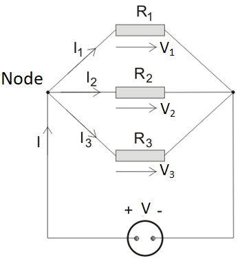
Figure 5: Parallel connection of three resistors
In general, the figure can be extended to parallel branches. When resistors are connected in parallel, the voltage across all resistors is the same and is equal to the source voltage :

The total current is equal to the sum of the currents through the individual resistors. This is Kirchhoff's 1st law.

Using Ohm's law  , we get:
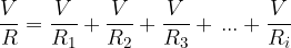
We divide both sides of the equation by and get:
is the total resistance because it is the resistance of the replacement resistor that would replace the parallel connection of all the resistors.
When resistors are connected in parallel, the voltage across all resistors is the same. The current is divided so that the total current is equal to the sum of the currents through the individual resistors. The reciprocal value of the total resistance is the sum of the reciprocal values of the resistances of the individual resistors.
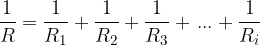
We connect three resistors in series and connect them to the voltage. The same current flows through all the resistors, and the source voltage is distributed among the resistors as shown in the figure.
Figure 6: Series connection of three resistors
Let us now extend the figure to series resistors. When resistors are connected in series, the current on all resistors is the same.

The sum of the voltages across the resistors is equal to the source voltage (Kirchhoff's 2nd law):

Using Ohm's law ( ), we obtain:

We divide both sides of the equation by  and get:

is the total resistance because it is the resistance of the resistor that would replace the series connection of resistors.
When resistors are connected in series, the current through all resistors is the same. The voltage is distributed across the resistors so that the total voltage (source voltage) is equal to the sum of the voltages across the individual resistors. The value of the total resistance is obtained by adding the values of the resistance of individual resistors:
Let's take an electrical conductor (e.g. a wire) of length  and cross-sectional area
  .
.
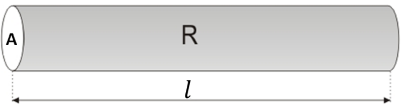
Figure 7: Resistivity of a conductor
In the material, Electric current, we saw that the electric current density  is proportional to the electric field strength
  and this expressed mathematically as:

where the proportionality constant  is called the specific conductivity.
Let's express the equation above in terms of the resistance :
The resistance of a conductor is directly proportional to the length and inversely proportional to the cross-sectional area of the conductor. The proportionality constant  (rho) is called the specific resistance or resistivity. It depends on the substance and is given in the table below. Silver (which is therefore the best electrical conductor) has the smallest resistivity, followed by copper, gold, aluminum, etc.

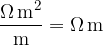
Let's make the resistivity the subject of the equation above and see what its unit is:

If we replace the quantities in the equation with their respective units, we will see that the unit of resistivity is given as:
The table below shows the resistivity of some metals:
The resistance of a conductor is directly proportional to the length of the conductor and inversely proportional to the cross-sectional area . The proportionality constant (rho) is called specific resistance or resistivity for short.
The current is measured by connecting an ammeter in series in the electrical circuit. The internal resistance  of the ammeter should be as small as possible so as not to reduce the current in the electrical circuit. An ideal ammeter has an internal resistance equal to zero.
The voltage across an element (e.g. a resistor) is measured by connecting a voltmeter in parallel to the element. The internal resistance  of the voltmeter should be as high as possible so that a negligible current flows through it. In this way, the voltmeter does not change the current in the electrical circuit. An ideal voltmeter has an internal resistance of infinity.
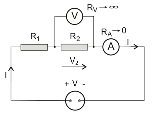
Figure 8 Voltage and current measurement
The voltage is measured with a voltmeter connected in parallel to the circuit element (voltage source or consumer). The current is measured by breaking the electric circuit and connecting an ammeter in series in the circuit.