Personal collections

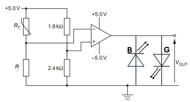
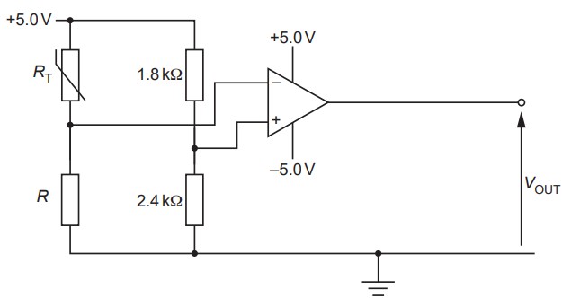
A circuit incorporating an ideal operational amplifier (op-amp) is shown in the figure below.
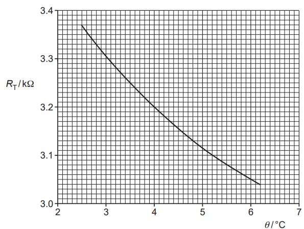
The variation with temperature  of the resistance
  of the thermistor is shown in the graph below.
The output potential  of the op-amp circuit changes sign when the temperature of the thermistor is
  . Calculate the resistance
  .
.
State and explain whether the output potential is  or
or  for a thermistor temperature of
  .
.
The output of the op-amp is to be displayed using two light-emitting diodes (LEDs) labelled G and B. When the temperature of the thermistor is below , only the LED labelled G emits light. The LED labelled B emits light only when the temperature of the thermistor is above . On the figure above, draw and label the symbols for the two LEDs.


 .
. . Thus,
  , and hence the output is