Personal collections

In the material, Electric field strength, we learned how to calculate the force on a charge in an electric field. We called it the electric force. Due to this force, the initially stationary charge begins to move with uniform acceleration in a straight line - in the direction of the electric field lines.
Let's now place an electrically charged particle in the magnetic field of a permanent magnet. We would expect that the magnetic field would also exert a force on the electrically charged particle and the particle would begin to move. The particle, however, remains at rest. First, let's conclude that the magnetic force does not act on charged particles at all.
The conclusion is only partially correct. The magnetic force is indeed zero if the charge is at rest. What if it moves? In this case, there is also a magnetic force.
In this material, we will learn to determine:
the magnitude and direction of the magnetic force on a moving, electrically charged particle,
the path of the particle's motion due to the magnetic force.
We will also get to know some devices that act on the basis of the magnetic force on moving charged particles. Devices like:
Hall element,
mass spectrometer,
circular accelerator or cyclotron.
An electrically charged particle flies into a magnetic field. The velocity  of the particle and the direction of the field
  should be perpendicular. Before it flew into the magnetic field, its motion was uniform and rectilinear. After entering a magnetic field, a magnetic force begins to act on it.
Let's take a closer look at how we determine the direction and magnitude of the magnetic force.
The magnetic force acts perpendicular to the direction of motion of the particles. The direction of the magnetic force can be determined in two ways.
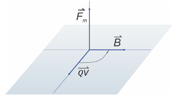
Right-hand screw rule
The direction of the force  is determined as the direction of motion of the right screw if we rotate the velocity vector
  along the shortest path into the magnetic field density vector
  .
.
Right hand screw rule
Left-hand rule
The direction of the force can also be easily determined using the left-hand rule, as shown in the figure below. The outstretched fingers are the direction of motion of positively charged particles, the lines of the magnetic field go into the palm, and the outstretched thumb shows the direction of the force.
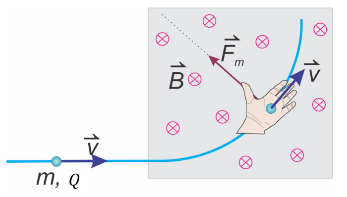
Left-Hand Rule
A circle with a cross at in the figure above means that the vector is directed away from the observer - that is, into the screen.
If the direction of motion of the particle is not perpendicular to the direction of the magnetic field, the magnetic force is still perpendicular to the velocity of the particle. However, the magnitude of the force is smaller (we learn how to calculate the magnitude of the magnetic force below). The magnetic force is caused only by that component of which is perpendicular to the speed .
Let's see how we calculate the magnitude of the magnetic force.
Through experiments, it's found that the magnitude of the magnetic force is directly proportional to the charge  and speed
  of the particle. The proportionality constant is the magnetic field density
  :
:
If the directions of the velocity of the particle and the magnetic field are not perpendicular, then we only consider:
the magnitude of the component of vector which is perpendicular to velocity or
the magnitude of that component of the velocity vector that is perpendicular to the magnetic field density .
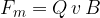
The magnitude of the magnetic force is calculated using the formula:
The magnetic force is perpendicular to the direction of motion of the particle. Its direction is determined with the help of a right-hand screw or the left-hand rule.
The magnetic force acts perpendicular to the direction of motion of the particle and causes a change in the direction of its motion. The particle is forced into circular motion. Since the force does not act in the direction of motion, it does not change the magnitude of the particle's velocity. It only changes the direction of the speed.
Let's remember Uniform circular motion. The force that changes the direction of motion of a body and forces it into a circular motion is called the centripetal force  or radial force
  . It is directed towards the centre of the circle. Even a particle flying at a constant speed into a magnetic field will circle due to the magnetic force. The magnetic force is therefore equal to the radial force and causes the particle to rotate uniformly.
Let's draw a figure of an electrically charged particle moving perpendicular to the lines of the magnetic field along a circular path:
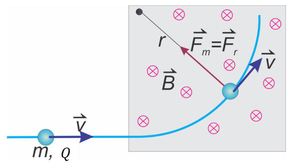
Path of rotation
During rotation, the resultant of the forces acting on the particle is equal to the radial force . Since the radial force is caused by the magnetic force  , it follows that:
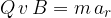
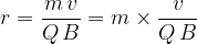
A particle that flies perpendicular to the lines of the magnetic field with a constant speed , makes a circle in the field. Here, the magnetic force is equal to the radial force :

or
Let's take a look at the following devices:
Hall element,
mass spectrometer,
circular accelerator of electrically charged particles.
We use the Hall element for:
determining the presence of a magnetic field (Hall sensor or sensor),
measuring the magnetic field density.
The Hall element consists of a plate - a cube with four connecting electrodes. It is usually made of a material called a semiconductor. This is, for example, silicon or germanium with added impurities. In a simplified way, we can imagine that the impurities determine whether the mobile charge carriers in the semiconductor will be positively or negatively charged particles.
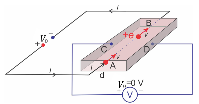
In the figure below, a semiconductor with positive moving charge carriers is selected. The direction of current in this case is the same as the direction of charge movement. Surfaces A, B, C, and D are metallized but do not touch.
The battery voltage  is connected between the surfaces A and B. Between the surfaces C and D, which are separated by
  , we measure the Hall voltage
  :
:
Hall element
In the absence of an external magnetic field, the charge carriers move straight from surface A to surface B, as shown in the figure above. Surfaces C and D remain electrically neutral, so the Hall voltage is zero.
Now we put the plate in a magnetic field. The strong magnetic field lines pierce the semiconductor wafer at right angles - figure below. The path of the motion of the positive charge is curved towards the left surface C due to the magnetic force, so surface C receives a positive charge  . Surface D reacts by accumulating an equal amount of negative charge
  on it.
An electric field of strength  is created between the two surfaces. This acts on the moving charged particle with an electric force, which is opposite to the magnetic force - the left figure below.
Charge on plates C and D builds up until the electric force becomes large enough to balance the magnetic force. Then the electric and magnetic forces are opposite and equal in magnitudes and therefore, their resultant is zero. Therefore, the charge carriers will then move straight towards surface B - the right figure below.
Hall element in the magnetic field
From the condition for the equality of both forces, we can calculate the Hall voltage.
The Hall voltage is therefore proportional to the magnetic field density , the speed of the charge carriers, and the distance between the plates (surfaces). With the known speed of the carriers and the spacing , we can calculate the magnetic field density by measuring the Hall voltage.
Mass spectrometer is a device that allows the analysis of the elements present in the jet of matter. The elements that make up the mass jet must have the same velocity and the same charge at the entrance of the mass spectrometer. They can only differ from each other in atomic or molecular masses.
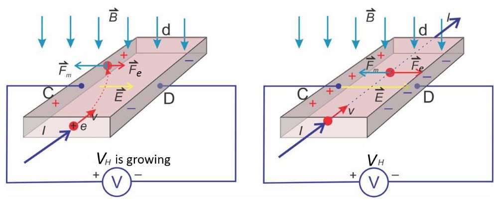
Dependence of radius of rotation on mass
Charged particles rotate after entering the magnetic field of density . The radius of rotation is proportional to the mass of the particle:
After about a quarter of a circle, they hit the screen, causing a trail of light to appear on the screen. From the spacing of the points on the screen (rotation radii), we conclude which chemical elements are present in the mass jet.
It is designed to accelerate electrically charged particles. Particles in the accelerator can reach speeds close to the speed of light. Accelerated particles can hit and break molecules or atoms of matter and thus give us insight into the structure of matter.
They are used for:
research in the field of molecules and atoms,
the synthesis of isotopes intended for industry and medicine.
During acceleration, particles can move along a straight path (linear accelerators) or along a circular path (circular accelerators). In this material we will look at a circular accelerator called a cyclotron.
The cyclotron has two hollow electrodes in the form of half cylinders. In cross-section, these are the blue hatched areas in the figure below. An alternating electric voltage is connected to them, which creates an alternating electric field in the space between the two half-cylinders. The AC voltage should be square-shaped so that the force on the particle is constant during acceleration.
Inside the half-cylinders is a magnetic field with density , which is caused by a coil. The magnetic field is directed in such a way that the path of the particles in it bends.
In the centre of the cyclotron is a source of electrically charged particles: electrons, protons, or ions - see the figure below.
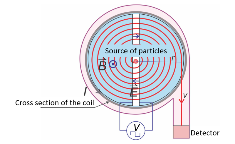
Cyclotron
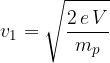
Suppose we are accelerating positively charged particles, e.g. protons. The particle is located at the centre of the cyclotron. According to the figure above, the electric field is first directed to the left and accelerates the protons. Their speed upon entering the left half cylinder can be calculated using the formula:
The proton in the left half cylinder bends and goes around half a circle on the magnetic field lines. The radius of the first semicircle is:

When the particle has traveled half of the circle, the sign of the alternating voltage is changed so that the particle is accelerated again in the space between the electrodes. The frequency of the alternating voltage must therefore be the same as the frequency of rotation of the particle.
After each passage through the gap between the two half-cylinders, the speed of the particles increases, and their radius of rotation also increases. The particle moves in a spiral - the red curve in the figure. At the exit of the cyclotron, it orbits at a radius  and reaches a speed .
Does the period and frequency of rotation change as the speed and radius of rotation increase? Let's derive the formula for the frequency of rotation.
We equate the magnetic force and radial force :
The frequency and period of rotation of a particle with mass  and charge do not depend on the current speed of the particle or the current radius of rotation, but only on the magnetic field density .
The advantage of the cyclotron is that it is possible to achieve high particle velocities with a relatively small device. When accelerating protons, particle velocities of up to a tenth of the speed of light can be achieved.