Personal collections

Lenses are optical devices that exploit the advantage of refraction of light. When light from the air hits glass or any other substance, where the speed of light propagation is lower than the speed in air (or an airless space), the beam is refracted towards the point of incidence - perpendicular to the air-substance boundary.
The image of an object obtained with the help of a lens can be real or virtual. In our ray diagrams, we will therefore mark the rays that give a real image with a solid line, and the imaginary rays that give a virtual image with a broken line. We will learn what is a real and what is a virtual image of an object using concrete examples.
Convex or converging lenses and concave or diverging lenses are used for imaging. In our discussion, we will assume that the lenses are thin, which means that the thickness of the lens is much smaller than the focal length.
A converging lens can be a combined section of two glass spheres in the middle. It is convex to the touch, its thickness in the middle is always greater than the thickness at the edges - which is schematically shown in Figures 1 to 8.
A beam of light rays parallel and close to the principal axis that is incident on a convex lens converges into a single point called the focal point or principal focus denoted by F on the principal axis after refraction.
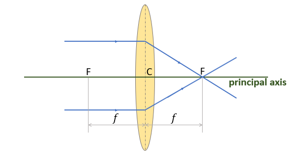
Figure 1: Principal axis and focus
Let us now look at some of the terms we use in all lenses (not just convex ones) and they are indicated in Figure 1.
Basic terms in lenses:
The optical centre: This is the centre of the lens and is denoted by C.
The principal axis: This is a line passing through the centre of the lens and perpendicular to the surface of the lens.
The principal focus: This is also called the focal point or simply focus. It is the point at which all rays parallel and close to the principal axis converge or appear to diverge after refraction. It is denoted by F. A lens has two foci - left and right of the centre of the lens.
The focal length: This is the distance between the optical centre and the principal focus.
The focal plane: This is the plane pierced by the optical axis perpendicular to the focal point. At a point (focus) lying on the focal plane, bundles of parallel rays, incident on the lens at a certain angle, converge.
Convex lenses are used for producing images of objects. An object of height  is placed at a distance
  in from the lens. At a distance
  from the lens, we get an image of height
  . The image can be reduced, the same size, enlarged, upright, inverted, real, or virtual depending on the position of the object. If the image is created by real rays, the image is real, but if the virtual rays intersect, the image is virtual.
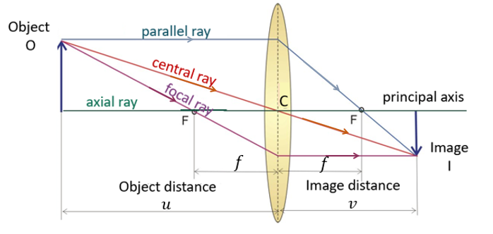
Figure 2: Image formation by convex lens
The rays shown in Figure 2 have the same name for both convex and concave lenses.
Types of rays in a ray diagram:
Axial ray: This is a ray along the principal axis. It maintains its direction after passing through the lens.
Central ray: This is a ray that passes through the centre of the lens at a certain angle to the principal axis. It maintains its direction after passing through the lens.
Parallel ray: This is a ray that is parallel to the principal axis. It passes through the principal focus on the other side of the lens after refraction.
Focal ray: This is a ray that passes through the principal focus. It travels parallel to the principal axis on the other side of the lens after refraction.
If we look at Figure 2, the image I of the object O is real (the real rays intersect), reduced, and inverted.
The lens equations relate the heights of the image and the object, their distances from the lens, and the focal length. The equations of a convex lens (which also apply to a concave lens) are obtained from the similar triangles in Figure 3:
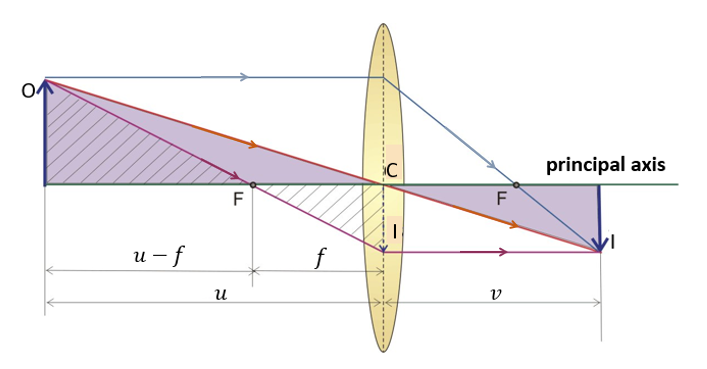
Figure 3: Lens equation - the rays form similar triangles
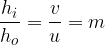
First, we observe the purple-coloured triangles. We see that the heights of the object and the image are in the same ratio as their distances from the apex of the lens:
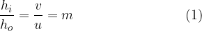
where  is the magnification of the lens, is the height of the object O, and is the height of the image I.
Let us now observe shaded similar triangles. We obtain the following:
The lens equations are:

where:
is the height of the object,
is the height of the image,
is the distance of the object from the lens,
is the distance of the image from the lens,
 is the focal length of the lens and
is the magnification of the lens.
If the image is inverted, we take the image height to be positive; if the image is upright, its height will therefore be negative.
The image distance and focal length can be positive or negative:
The image distance is negative if it is formed by the apparent intersection of rays i.e. a virtual image (see the example in Fig. 8).
The image distance is positive if it is formed by the actual intersection of rays i.e. a real image.
The focal length of a converging lens is positive while that of a diverging lens is negative (Fig. 9).
The type of image formed by a convex lens depends on the distance of the object to the lens, as shown by the following examples:
We place the object at a distance greater than 2 F before the lens. Three rays are drawn from the object to the lens:
The first ray is parallel to the principal axis and it passes through the principal focus after refraction from the lens (parallel ray).
The second ray is at an angle to the principal axis and it passes through the optical centre of the lens undeviated after refraction from the lens (central ray).
The third ray passes through the principal focus and travels parallel to the principal axis after refraction from the lens (focal ray).
The image is formed between F and 2 F by the intersection of the refracted rays on the other side of the lens.
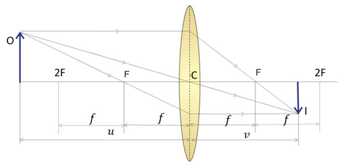
Figure 4: convex lens - Example 1
The image is real, diminished, and inverted.
We place the object at 2 F before the lens. Three rays are drawn from the object to the lens.
The first ray is parallel to the principal axis and it passes through the principal focus after refraction from the lens (parallel ray).
The second ray is at an angle to the principal axis and it passes through the optical centre of the lens undeviated after refraction from the lens (central ray).
The third ray passes through the principal focus and travels parallel to the principal axis after refraction from the lens (focal ray).
The image is formed at 2 F by the intersection of the refracted rays on the other side of the lens.
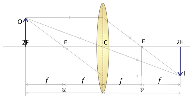
Figure 5: convex lens - example 2
The image is real, the same size as the object, and inverted
We place the object between F and 2 F before the lens. Three rays are drawn from the object to the lens.
The first ray is parallel to the principal axis and it passes through the principal focus after refraction from the lens (parallel ray).
The second ray is at an angle to the principal axis and it passes through the optical centre of the lens undeviated after refraction from the lens (central ray).
The third ray passes through the principal focus and travels parallel to the principal axis after refraction from the lens (focal ray).
The image is formed beyond 2F by the intersection of the refracted rays on the other side of the lens.
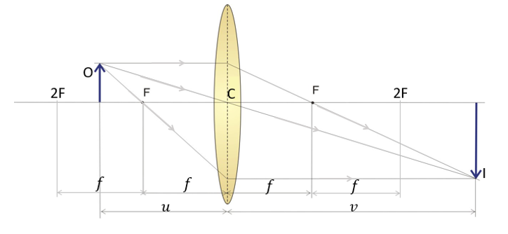
Figure 6: convex lens - example 3
The image is real, enlarged, and inverted
We place the object at F before the lens. Two rays are drawn from the object to the lens.
The first ray is parallel to the principal axis and it passes through the principal focus after refraction from the lens (parallel ray).
The second ray is at an angle to the principal axis and it passes through the optical centre of the lens undeviated after refraction from the lens (central ray).
The refracted rays do not intersect since they are parallel to each other after refraction. Therefore no image can be formed.
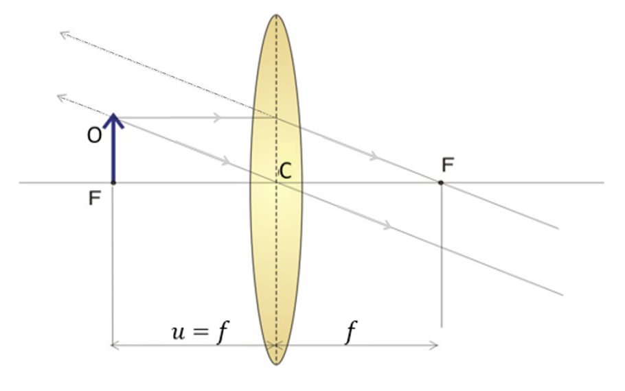
Figure 7: convex lens - Example 4
Both the actual and apparent rays are parallel therefore no image is formed.
We place the object between the principal focus F and the optical centre C of the lens. Two rays are drawn from the object to the lens.
The first ray is parallel to the principal axis and it passes through the principal focus after refraction from the lens (parallel ray).
The second ray is at an angle to the principal axis and it passes through the optical centre of the lens undeviated after refraction from the lens (central ray).
The refracted rays do not intersect as they are scattered after refraction but the virtual rays intersect on the side of the object. Therefore an image is formed at the same side of the lens as the object.
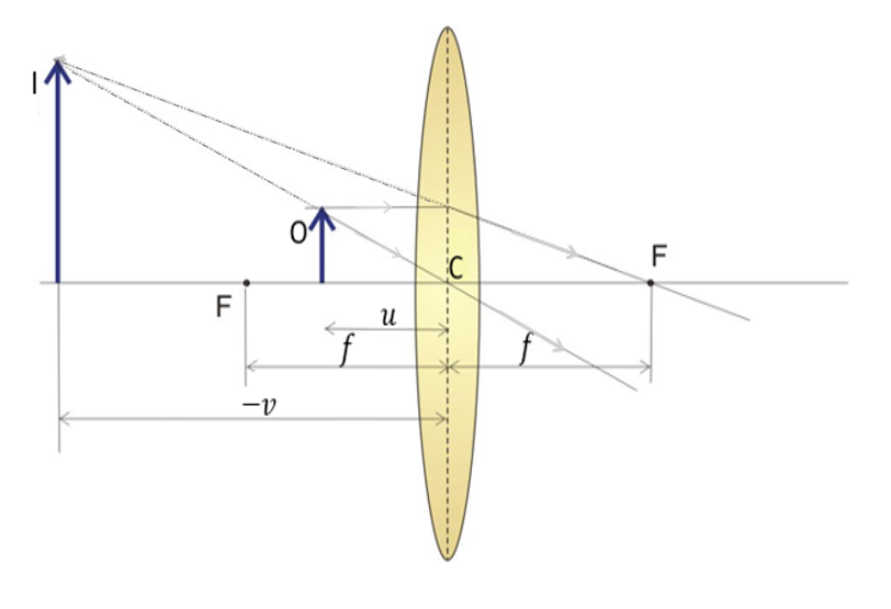
Figure 8: convex lens - Example 5
Real rays on the other side of the lens are scattered. On the same side as the object, the virtual rays intersect to form a virtual image. The image is enlarged and upright.
Application example: magnifier (magnifying glass)
In this case, the focal length is still positive while the height and distance of the image are both negative.
A concave lens is made up of two inner, concave parts of spherical sections. The lens is concave to the touch, its thickness in the middle is less than the thickness at the edges. It is shown schematically in Figure 9.
In the case of a concave lens, the rays are scattered after passing through the lens. Real rays will never intersect. However, the virtual rays intersect and are shown as an extension of the real rays on the side of the object - Figure 9. We mark them with a dashed line. The image is therefore virtual. From Figure 9 we also understand that the image of the object is upright and diminished.
The equations of the lens, which we derived for a convex lens, still apply, but we must take note that the focal length is negative. Therefore, in our calculations (see example), we will see that and will also be negative.
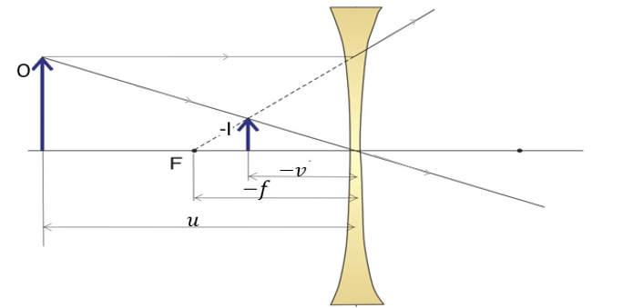
Figure 9: Image formation by a concave lens
The image is on the same side as the object. The distance of the image from the lens is always less than the distance of the object from the lens. Since both distances are in the same ratio as the heights of the image and the object (see lens equation), it follows that the image is also smaller than the object.
The image is always virtual with a concave lens, as the actual rays on the other side of the lens are scattered. The image is upright, and the focal length and distance of the image from the lens are negative.


The absolute value of the distance of the image from the lens is always less than the distance of the object:

It follows that the size of the image is always smaller than the size of the object since the equation below holds:
The lenses can be arranged one after the other to obtain compound lenses. Convex lenses  , concave lenses
  or combinations of both can be assembled. We assume the lenses are thin and close together.
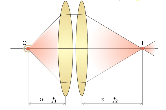
Figure 10: Compound lenses
As an example, we take two convex lenses as shown in Figure 10. We place a point light that serves as the object O at the principal focus of the first lens. The rays emanating after refraction from the first lens give a parallel beam of light between the two lenses which is then incident on the second lens. After refraction from the second lens, the rays converge at the focus of the second lens, where we get an image I of the lamp.
Let's apply the lens equation:
We obtained the focal length of the combination of the two convex lenses.
For compound lenses, the reciprocal of the focal length is the sum of the reciprocals of the focal lengths of the lenses:
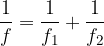
The reciprocal of the focal length is also called the power of a lens, its unit is dioptre. So we can say that the powers are added when the lenses are combined.
The power of a lens is the reciprocal of the focal length of the lens. The smaller the focal length of a lens, the more powerful it is. A convex (converging) lens has a positive focal length therefore it has a positive power value. A concave (diverging) lens has a negative focal length therefore it has a negative power value. The power of a lens is measured in dioptres, denoted by D. The term dioptre is used by opticians to construct lenses. The dioptre of a lens depends on the radius of the spherical glass of which the lens forms a part, the refractive index of the substance, and the thickness of the lens; you can read more about dioptres in the material Power of a lens.
The power p of a lens is given as:

Therefore,  or
or 
If we have several lenses placed one after the other, we found in the previous section that the reciprocals of the focal lengths are added:
or, if we are to express the equation in dioptres, the dioptres of individual lenses will also be added when assembling lenses:
Examples of compound lenses are glasses, camera lenses, etc., which are described in more detail in the material Optical devices.