Personal collections

If we grab the rim of a car's steering wheel and turn it, we act on it with a force  , which acts in the direction of rotation of the steering wheel (see Figure 1). The direction of the force is therefore tangent to the circle represented by the steering wheel. The steering wheel rotates around the centre of the circle, which is called the axis of rotation or pivot point.
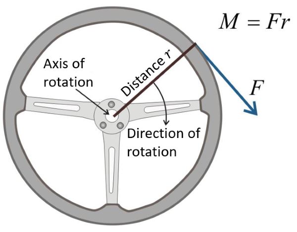
Figure 1: Torque force on the steering wheel of a car steering
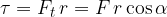
The product of the force with which we act on the steering wheel and the perpendicular distance between the force and the pivot point, which is equal to the radius  wheel, is called torque
  :
:

The written equation is valid only if the force and the distance are perpendicular.
The higher the torque, the higher the force and/or distance.
We give the torque a positive or negative sign, depending on the direction of rotation. The sign for a certain direction of rotation can be chosen arbitrarily. We decide that clockwise rotation is positive and counterclockwise rotation is negative. This is in accordance with the direction in which the screw that is screwed into e.g. wood, is rotated:
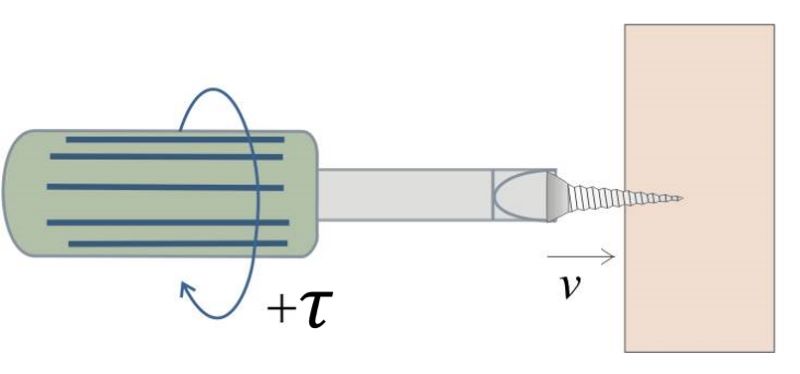
Figure 2: The screw that is turned to the right is screwed into the object. Torque is positive.
The unit of torque is  (pronounced: Newton metre).
Torque is the product of force and perpendicular distance :
Torque can be positive or negative. The sign depends on the direction of rotation and can be chosen arbitrarily. In this chapter, we will consider that the positive torque is the torque that twists in the direction of rotation of the right-hand screw that is screwed into an object (i.e. clockwise).
In this material, we will learn:
how to calculate the torque even if the force and the distance are not perpendicular;
how torque acts on a body;
how to add and subtract torques;
about the balance of forces and torques;
what the centre of gravity of a body is. For simple cases, we will also calculate it.
Torque is actually a vector. It has its own magnitude and direction. It is directed in the direction of the vector product of the force and the perpendicular distance:

The torque is perpendicular to the plane on which the vectors  and
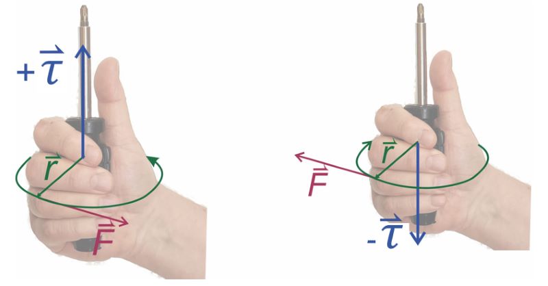
and  lie as shown in the figure below. How do we determine the direction of the torque vector? One option is to grasp an object (e.g. a screwdriver) with the right hand and turn it clockwise. The outstretched thumb indicates the direction of positive torque - the left figure. The sign of the torque changes if we rotate in the opposite direction - the right figure.
In this material, for simplicity, we will consider torque to be a scalar (a number). In this case, we can arbitrarily choose which torque is positive and which is negative. We define:
torque as positive if it tries to rotate clockwise;
torque as negative if it rotates counterclockwise;
Let's write the formula of torque again without the vector sign:
Torque is the product of force and the perpendicular distance. The force and the distance must be perpendicular. If this is not true, we have two options:
we calculate the component of the force that is perpendicular to the distance or
we calculate the component of the distance that is perpendicular to the force.
Let’s take a closer look at both options.
Let's calculate the torque when we have a given force and a distance that are not perpendicular to each other. We know that torque is greatest when a given force acts perpendicular to the distance. If the force is not perpendicular to the distance, we need to find the component of the force that is perpendicular to the distance - see Figure 3.
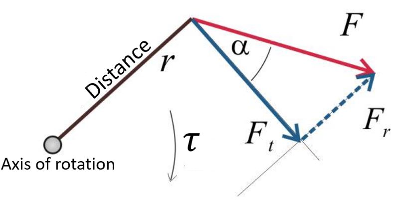
Figure 3: Torque is caused by the perpendicular component of the force
We denote the angle between the direction of the force and the component perpendicular to the distance by  . Force is resolved into two components:
The first component is parallel to the distance
In Figure 3, it is marked with  .
.
It is calculated using the sine of angle which is given as:
This component has the same direction as the distance and therefore does not produce torque.
The second component is perpendicular to the distance
In Figure 3, it is marked with  .
.
It is calculated using the cosine of the angle which is given as:
This component points in the direction of the tangent of the circle of rotation, so it is called the tangential force. The tangential force causes torque.
The general equation for torque is written as:
The torque is caused by the component of the force perpendicular to the distance. If we denote the angle between the direction of the force and the component perpendicular to the distance by  , then the torque is calculated using the equation:
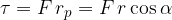
In this case, we will calculate the torque when we have a given force and a distance that are not perpendicular to each other. With the difference that we will now move the force along its axis so that it is perpendicular to some new distance  (see Figure 4):
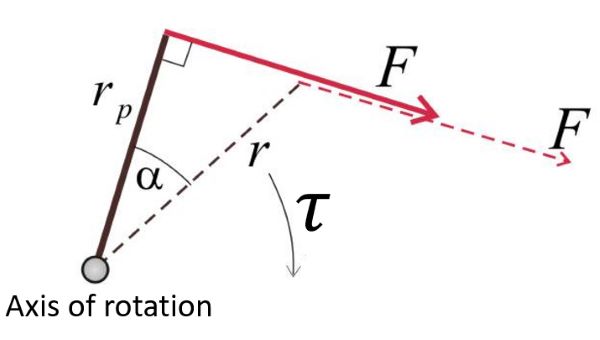
Figure 4: The distance component is perpendicular to the force
The angle between the previous and new distance is again denoted by .
Let's calculate the torque:
We can move the force along its axis so that it is perpendicular to some new distance  . The torque in this case is calculated using the equation:
Several torques may be applied to a body. The sum or resultant of the torques acting on the body is obtained by adding them up.
The sum of n torques is given as:

When adding torques, we must pay attention to the sign of the torque. Let's recall that:
if the torque causes clockwise rotation, the torque is positive.
if the torque causes a counterclockwise rotation, it is negative.
In the material, Force as a vector, we learned that a body is in equilibrium if the sum of the forces acting on the body is zero. In this case, the body is stationary or moving uniformly and in a straight line.
What if the sum of the forces is zero and the sum of the torques is nonzero? In this case, the torque is caused by the rotation of the body. The body rotates with uniform acceleration. We will learn about this example in the material, Angular momentum.
In this material, we will limit ourselves to the case where the sum of all forces and the sum of all moments of forces (torques) is equal to zero. The body is then in mechanical equilibrium. This means that it does not move and does not rotate (or that it moves uniformly and in a straight line and rotates uniformly).
If a body:
does not move or rotate or
moves uniformly and in a straight line or rotates uniformly,
it is in mechanical equilibrium. The condition for mechanical balance is that the sum of all forces acting on the body and the sum of all moments is zero:


A spiral spring is an elastic steel strip wound in the shape of a snail. It is used in analog clock watches, measuring instruments for measuring electrical quantities, as well as for torque measurements. Figure 8 shows the operation of a spiral spring:
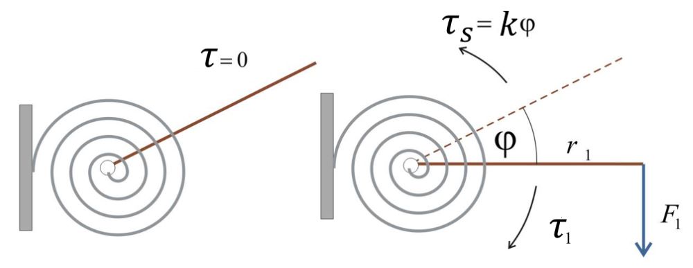
Figure 8: Spiral spring torque
Let us describe what is happening in Figure 8: the outer end of the coil spring is attached to a support. A lever is attached to the centre of the spring so that it is rotatable around an axis in the centre of the spring. The spring is initially in equilibrium and there is no torque on it (Figure 8, left).
Then we start applying a force  on the free end of the lever of length
  . This creates a torque
  which is given as:

But the given torque is resisted by the torque  of the spiral spring (Figure 8, right). Through measurements, we find that the torque of a spiral spring is proportional to the angle of rotation
  (as given in radians). The proportionality factor is the spring constant
  and we can write the formula for the spiral spring torque as:

In equilibrium, both torques will be equal:

or:

If we rotate a spiral spring by an angle with the external torque, the spring works back with equal but opposite torque:
The unit for angle is the radian.
One of the forces that causes torque is the weight of a body. So far we have considered cases where:
the weight body was small;
the distance was, compared to the size of the body, large.
The torque of the weight of such a body with mass  and perpendicular distance was calculated using the equation:
Now let's take a body with mass , which has a higher weight compared to the distance . The torque can no longer be easily calculated according to the previous formula since each part of this body has a different distance and thus contributes a different value to the total torque of the force of gravity (weight) (see Figure 9).
We tackle such a problem by dividing the body into infinitesimally small masses, each with its own weight. To make calculations easier, let's take n small masses, where n is a large number. We choose the pivot point of the body and calculate the torques of the weight forces of the individual masses (Figure 9, left). We must make sure that the forces of gravity and the levers are perpendicular, so we move the forces of gravity along their axes so that they are perpendicular to the levers (Figure 9, right).
For the clarity of the image, we draw the body in two dimensions:
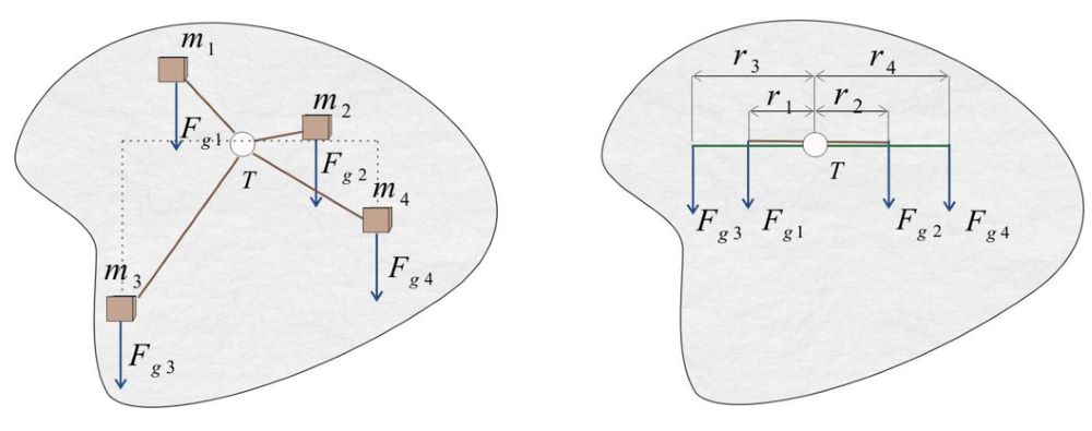
Figure 9: Calculation of the torque of weight
Let's calculate the sum of the torques in the pivot T according to Figure 9:
Let's introduce the centre of gravity: the centre of gravity is that point of the body that, if we place a fulcrum (pivot) in it, all the torques of the force of gravity (weight) of the given body will add up to zero.
If the point T in Figure 9 is placed in the centre of gravity, the equation above becomes:
The centre of gravity of a body is the pivot point where the torque of the body's weight sums to zero. In other words: the sum of the torques of the weights of all partial masses that make up the body is equal to zero if the pivot is placed in the centre of gravity of the body.
The centre of gravity can also be thought of as the point where (for calculation purposes) all the mass of the body is combined.
Finding the centre of gravity of a body can be made easier by hanging the body on a thin string and waiting for it to rest. The direction of the string is the line around which all torques of the force of gravity are in equilibrium, regardless of where on the line the axis of rotation is taken. The straight line is called the centroid. If you wanted to get the centre of gravity, you would repeat the experiment several times and each time, hang the body in a different place, as shown in the picture. At the intersection of the lines, you would get the centre of gravity - Figure 10.
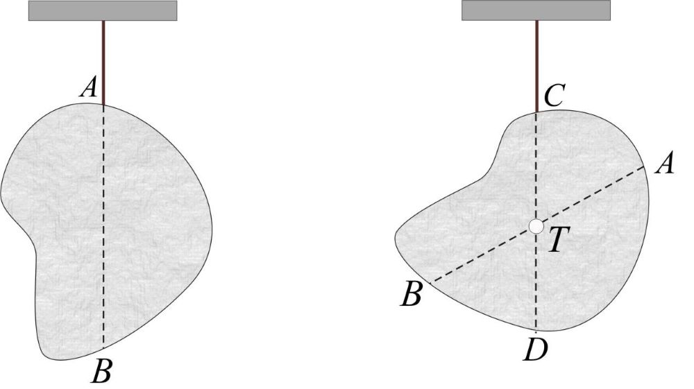
Figure 10: Finding the centre of gravity of a body using the string on which we hang the body
The torque of the weight of a geometric body is calculated by thinking of the entire mass of the body as collected in one point, which is in the body's centre of gravity. Such a body is called a point body.
Let's look at some bodies for which we intuitively know where their centre of gravity is:
We know that a cube has its centre of gravity in the centre - that is, the intersection of the diagonals of the body.
A sphere has its centre of gravity at its centre.
A cylinder has its centre of gravity in the middle of its geometric axis.
In addition to known objects, the centre of gravity can be determined by experimenting with a string to any geometric body. The torque of the weight of the geometric body is calculated according to the formula:

and we must take into account in the formula that the distance is the distance between the pivot point and the centre of gravity of the body.
When calculating the torque of a body, we must take the distance between the pivot point and the centre of gravity of the body as the lever.
Let us have n point bodies. The centre of gravity of the system of point bodies is calculated according to the following steps:
First, we choose a pivot point.
Then we calculate the torques of the weights with respect to the selected axis of rotation and add them up:

The torques of the weights of all masses are equal to the "replacement" torque. The distance  of the replacement torque is just the distance between the pivot point and the centre of gravity, and the mass of the replacement torque is the total mass of the system:

Let's make the subject of the formula:
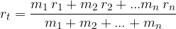
The distance of the centre of gravity to the selected pivot in the case of point bodies arranged along a straight line is:
Where  ,
,  , ...,
  are the masses of point bodies and
  ,
,  , ...,
  are their distances from the selected pivot point.