Personal collections

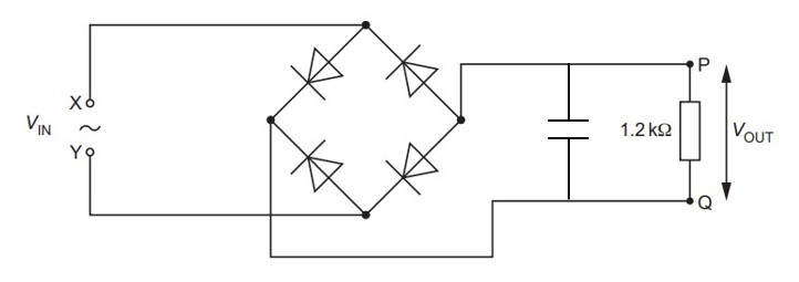
The figure below shows four diodes and a load resistor of resistance  , connected in a circuit that is used to produce rectification of an alternating voltage.
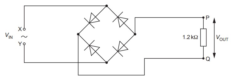
State what is meant by rectification.
State the type of rectification produced by the circuit in the figure above.
A sinusoidal alternating voltage  is applied across the input terminals X and Y. The variation with time
  of is given by the equation

where is in volts and is in seconds.
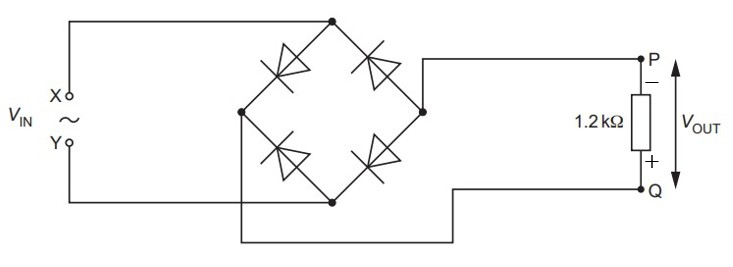
On the figure above, label the output terminals P and Q with the appropriate symbols to indicate the polarity of the output voltage  .
.
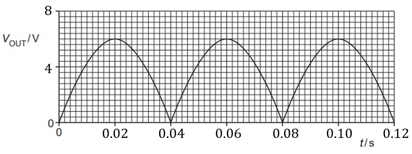
The magnitude of the output voltage varies with as shown in the graph below.
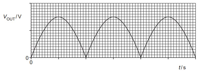
On the graph above, label both of the axes with the correct scales. Use the space below for any working that you need.
The output voltage in (b) is smoothed by adding a capacitor to the circuit in the figure above. The difference between the maximum and minimum values of the smoothed output voltage is  of the peak voltage.
On the figure above, draw the circuit symbol for a capacitor showing the capacitor correctly connected into the circuit.
Calculate the capacitance  of the capacitor.


 .
.