Personal collections

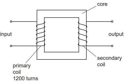
An ideal transformer is shown in the figure below.
Explain
why the core is made of iron,
why an electromotive force (e.m.f.) is not induced at the output when a constant direct voltage is at the input.
An alternating voltage of peak value  is applied across the 1200 turns of the primary coil. The variation with time
  of the e.m.f.
  induced across the secondary coil is shown in the graph below.
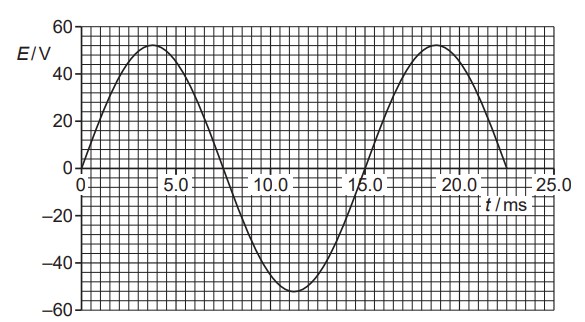
Use data from the graph above to
calculate the number of turns of the secondary coil,
state one time when the magnetic flux linking the secondary coil is a maximum.


 or
or  or
or  or
or  .
.