Personal collections

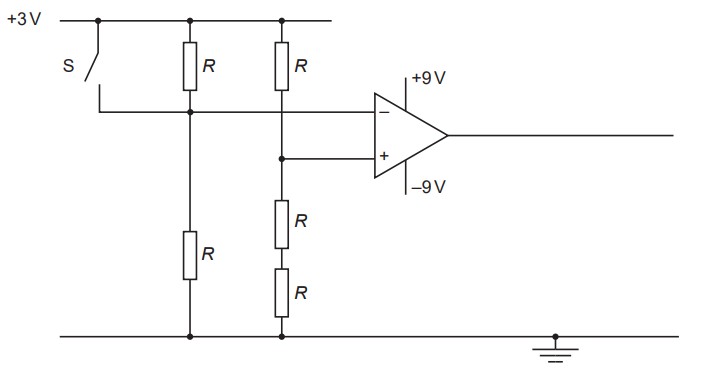
A circuit incorporating an ideal op-amp is to be used to indicate whether a door is open or closed. Resistors, each of resistance  , are connected to the inputs of the op-amp, as shown in the figure below.
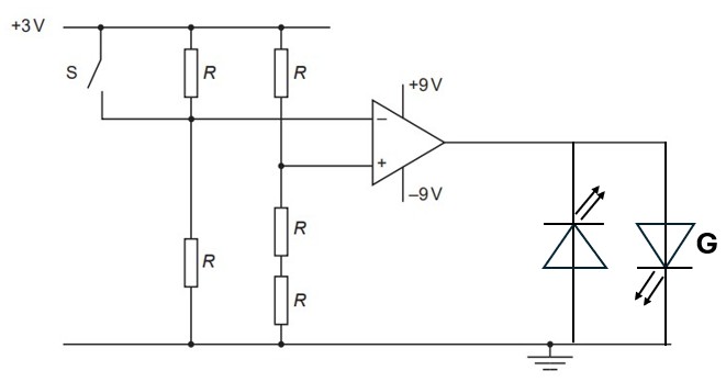
The switch S is attached to the door so that, when the door is open, the switch is open. The switch closes when the door is closed. A red light-emitting diode (LED) is to be used to indicate when the door is open. A green LED is to indicate when the door is closed. On the figure above,
draw symbols for the LEDs to show how they are connected to the output of the op-amp,
identify the green LED with the letter G.