Personal collections

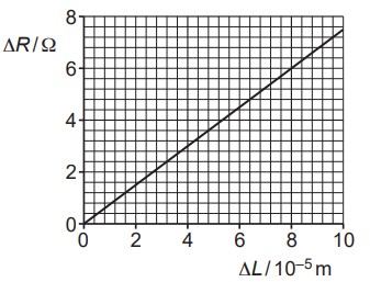
In a strain gauge, the increase in resistance  depends on the increase in length
  . The variation of with is shown in the graph below.
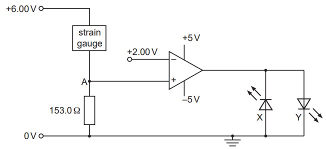
The strain gauge is connected into a circuit incorporating an ideal operational amplifier (op-amp), as shown in the figure below.
The strain gauge is initially unstrained with resistance  . Use data from the graph above to calculate the increase in length of the strain gauge that gives rise to a potential of
  at point A in the figure above.
The strain gauge undergoes a further increase in length beyond the value in (a). State and explain which one of the light-emitting diodes, X or Y, will be emitting light.


 .
. . This implies that the output is negative, and hence, the light-emitting diode X will be emitting light.